Lab 8: Stunts
5 minutes read •
Flip Implementation
Bluetooth Data Transmission
The entire flip program starts when called over bluetooth via the Jupyter notebook line: ble.send_command(CMD.STUNT, "1200"). The parameter passed in is the distance away from the wall that the car should begin to reverse at. Note that 1200 mm is larger than the distance away from the wall of the mat (300 mm) as the car needs time to slow down before ultimately flipping on the mat. This parameter allows for easy flip tuning for various different starting positions and flip locations.
Arduino Code
The STUNT command is responsible for ensuring the first kalman filter value is stored and calling the essential Flip() and sendStuntData() functions. Here is the command:
stuntStartTime = ;
// Loop until first kalman value is recieved
while
// Stunt logic
;
;
;
The functions to note are:
Flip()runs the logic to drive at the wall then flip the robot. While the robot has yet to reach the flip distance, it drives forward at full speed. Once it reaches the target distance, it runs in reverse at full speed for 2300 ms. Note that during both loops, ToF and Kalman data is being collected.
if
if
;
collectTOF()responsible for collecting current ToF values and updating the globalTOF1array with distancesgetKalmanData()reads in the currentTOF1array value (updated by the collectTOF() function). In return it updates the globalkfarray with the kalman filter calculated distance which is used for tracking distance to the wall for the stunt. In the below code, you can see the use of an update flag that flips based on whether new sensor data is ready– this helps to speed up the process. The following A and B matrices were used post tuning:
if
else
sendStuntData()loops through crucial arrays and sends them over bluetooth to be processed by the notification hanlder and piped into a csv for graphing and post prosessing.
Results
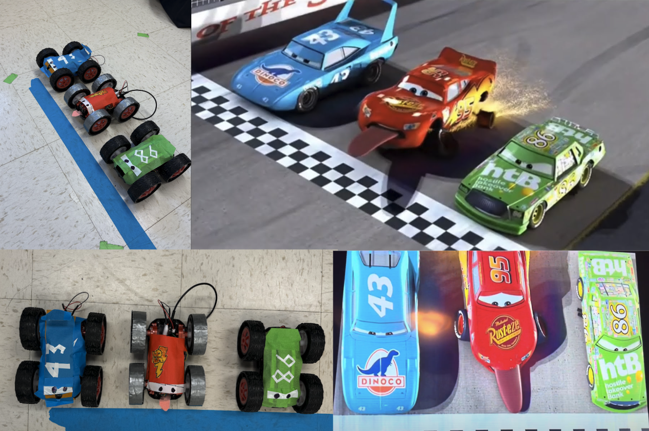
Stunt Videos
The time elapsed for each stunt trial are in the image captions; the timer starts once the car passes the blue line and ends once it retuns and crosses it.
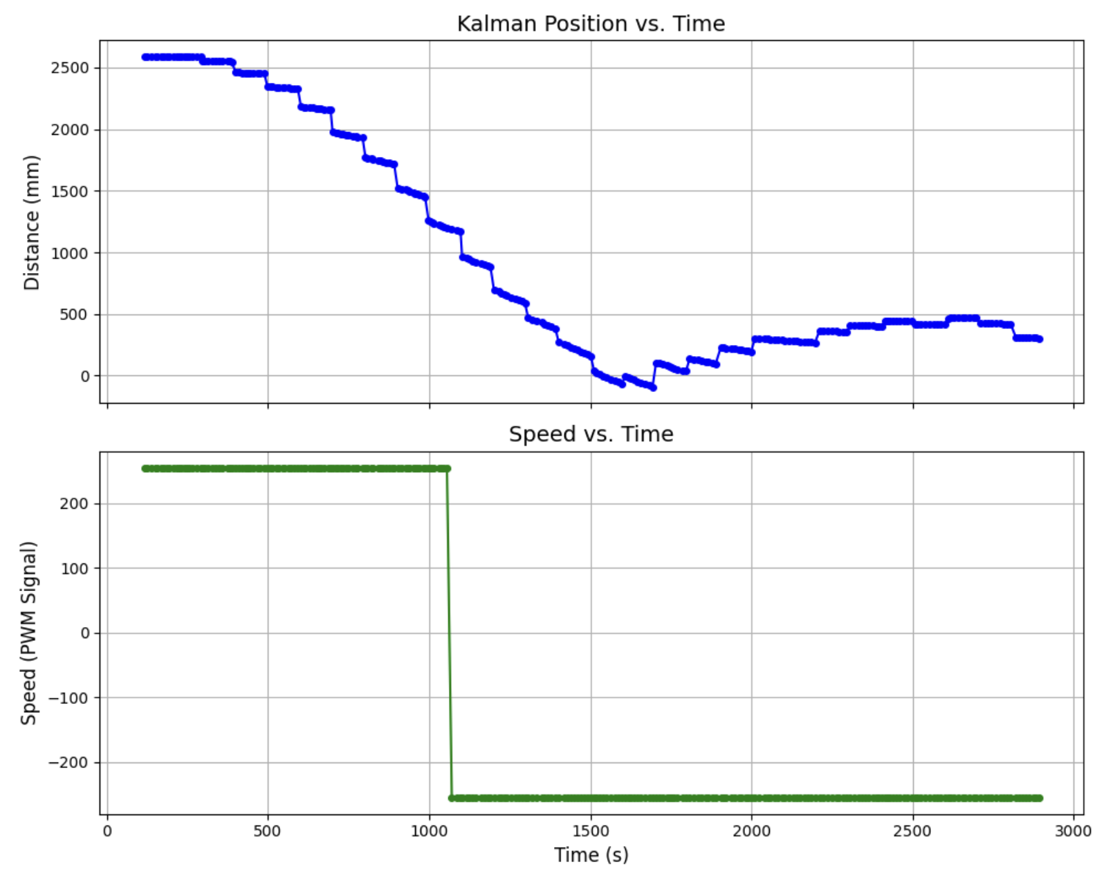
Graphs for Trial 3
From the graph you can see Kalman Filter Position vs. Time as well as Speed vs. Time. Note that the speed flips from 255 to -255 once the robots hits the target distance of 1200 mm. This distance was played around with until finally deciding that 1200 mm was just enough to have the robot flip on the mat (300 mm from the wall) without hitting the wall or flipping too early. You can see that the Kalman filter could use some further tuning as the model predicts too slow of a velocity (as seen from the lack of steepness in the bunched up data). Returning to the state space model, this could be improved by reducing m (to increase the B matrix) or increasing U (less intuitive fix). ToF sensor data is visible from the KF jumps but aren’t shown to reduce graph clutter.
Blooper Video
Here is my blooper video! (Here is the original but vote on the edited cars version)
Summary and Challenges
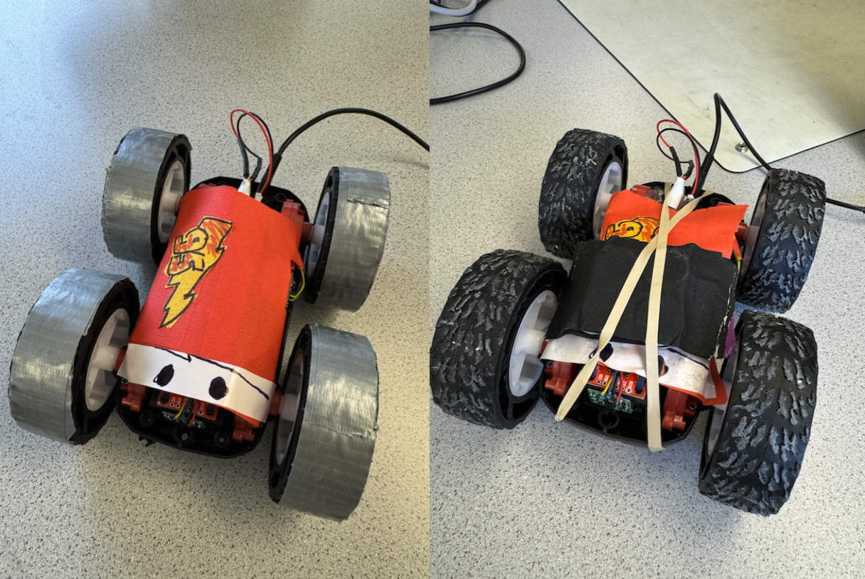
- You can see that in two of the trials, an added weight is mounted to the front of the robot to help it nosedive and flip about its front. By the end I realized that the added mass did not help as much as a fully charged battery thus you can see that the trials with the added weight (1 and 2) are nearly identical to those without. The weight was made out of taped together washers and was shared between Trevor and I.
- Throughout the hours of testing, I had to use correction factors to straighted the car’s trajectory toward the mat and also help to slow the wheels down at the same time, ensuring that when flipped, the robot was oriented straight. My correction terms scale the passed in PWM speed. When driving at the wall, a correction term of 0.95 scales the right side motor and when driving in reverse (slowing down) a correction factor of 0.90 scales the left side motor. The blooper is an example of the robot before tuning. You can see it arc left when approaching the wall and then spinning as it slowed down which made it ultimately return at the completely wrong angle.
Collaboration
I collaborated extensively on this project with Jack Long and Trevor Dales. ChatGPT was used to help plot graphs.